
Corrugated metal panel
History and Development of Corrugated Metal Panels
Corrugated metal panels have a rich history that traces back to early 19th-century England. The innovation is credited to Henry Robinson Palmer, an architect and engineer for the London Dock Company, who patented "indented or corrugated metallic sheets" in 1829. Palmer's invention addressed the need for lightweight yet strong roofing materials for large warehouses and industrial buildings. The first major application was the Turpentine Shed, built around 1830, which showcased the panels' structural efficiency and ease of installation.
The technology quickly spread, with corrugated iron sheets being used in prominent structures such as railway stations, gasworks, and factories throughout the United Kingdom and beyond. The panels were praised for their ability to span wide roofs with minimal support, their portability, and their cost-effectiveness. By the mid-19th century, corrugated metal had become a global industrial standard, especially after the expiration of Palmer’s patent in 1843, which led to widespread manufacturing and adoption.
Intended Applications and Early Uses
Originally, corrugated metal panels were intended for roofing large industrial and commercial buildings, where their strength-to-weight ratio and ease of installation were significant advantages. Their inherent corrugated shape provided structural rigidity, allowing for longer spans and lighter framing. The panels also offered natural water drainage, making them ideal for roofing. Some architectural examples by Glenn Murcutt here
Corrugated metal soon found use in a variety of applications:
Industrial buildings (warehouses, factories)
Railway stations and infrastructure
Military structures (notably Nissen and Quonset huts during World Wars I and II)
Rural and agricultural buildings (barns, sheds, silos)
Prefabricated and temporary structures
Residential homes, particularly in regions like Australia and New Zealand
Material Evolution and Technological Advancements
The earliest corrugated panels were made from wrought iron, but by the late 19th century, mild steel became the preferred material due to its improved strength and manufacturability.Corrosion was initially a problem, but this was largely solved by hot-dip galvanizing the panels with zinc or tin, which also gave them a distinctive sheen.
Throughout the 20th century, advances in rolling and forming technology allowed for mass production and more varied profiles. The development of roll-forming machines enabled the production of panels for new uses, such as livestock water tanks and prefabricated garages.Later, aluminum and coated steel became popular for their corrosion resistance and lighter weight.
Perforated Corrugated Metal Paneling: Development and Uses
Perforated corrugated metal panels are a modern evolution, combining the structural benefits of corrugation with the functional and aesthetic advantages of perforation. The process involves mechanically stamping or laser-cutting patterns of holes into flat metal sheets, which are then formed into corrugated shapes.
Key benefits and uses of perforated corrugated panels include:
Allowing airflow and light transmission while maintaining strength
Providing shade and ventilation in canopy or awning applications
Serving as acoustic panels for sound absorption and noise control
Acting as decorative elements in architectural facades and interior design
Functioning as screens, fences, and partitions that balance privacy with openness
Perforated panels are specified by pattern, hole size, and open area, which can be tailored to the desired balance of strength, transparency, and aesthetics. They are widely used in contemporary architecture for building cladding, sunscreens, and artistic installations, as well as in transportation, food processing, and filtration industries.
Modern Applications and Cultural Impact
Today, corrugated metal panels-both solid and perforated-are ubiquitous in construction worldwide. They are used for roofing, siding, fencing, enclosures, and even interior design accents. Their durability, low cost, and adaptability have made them especially important in affordable housing, disaster relief, and informal settlements.
In some regions, such as Australia and New Zealand, corrugated metal has become a cultural icon, featured in both utilitarian and high-end architectural projects. Advances in coatings, color options, and profile designs continue to expand their use in sustainable and energy-efficient building solutions.
Compliant Mechanism
A compliant mechanism is a flexible device that achieves force and motion transmission through elastic body deformation. Unlike traditional mechanisms that use rigid components and joints, compliant mechanisms gain their mobility from the deflection of flexible members. These mechanisms can be monolithic (single-piece) or jointless structures, utilizing the inherent elasticity of materials to perform desired functions.
Key Features
Flexibility: Compliant mechanisms rely on the elastic properties of materials to bend and deform, allowing for motion and force transmission.
Reduced Parts: They often consist of fewer components compared to traditional mechanisms, sometimes even being manufactured as a single piece.
Energy Storage: The flexible members can store and release energy, similar to springs.
Advantages
Simplicity: Fewer parts and assembly steps lead to simpler designs.
Cost-effectiveness: Reduced part count often results in lower production costs.
Precision: Elimination of backlash and wear can improve accuracy in motion.
Miniaturization: Compliant mechanisms are well-suited for micro-scale applications, such as MEMS devices.
Limitations
Limited Motion Range: The extent of movement is constrained by the material's elastic properties.
Fatigue: Repeated deformation can lead to material fatigue and potential failure.
Non-linear Behavior: The flexible nature of these mechanisms can result in complex, non-linear responses.
Compliant mechanisms are found in various everyday objects, including backpack latches, paper clips, plastic bottle caps, and computer mouse buttons. They are also used in more advanced applications such as precision manufacturing equipment and microelectromechanical systems (MEMS).
Bugle head screw

A bugle head screw is a type of fastener specifically designed for drywall applications and woodworking. It features a countersunk head with a flat top and a concave under-head bearing surface 15. This unique design allows the screw to sit flush with the material's surface while distributing the bearing stress over a wider area than a flat head screw 1.
The invention of the bugle head screw is not attributed to a single person, as it evolved from earlier screw designs. However, some key developments in screw technology led to its creation:
In 1933, Henry Phillips patented the Phillips head screw, which featured a cross-recessed design that improved upon earlier slotted screws 4.
In the 1950s, the U.S. Gypsum Corporation team, led by Paul Quigg, perfected the drywall screw, which was a precursor to the bugle head screw 8.
The bugle head screw was developed to address specific needs in construction and woodworking:
Reduced material damage: The trumpet-shaped head design effectively disperses pressure, minimizing damage to materials like drywall and wood 3.
Easy installation: The design eliminates the need for pre-drilling countersinking holes, saving time and effort during installation 15.
Strong fixing force: Bugle head screws provide a secure connection, ensuring stability in various applications 3.
Versatility: They are suitable for use with drywall, wood, and other lightweight materials, making them ideal for a wide range of construction and woodworking projects 3.
The development of the bugle head screw was driven by the need for faster, more efficient installation methods and improved holding power in different materials, particularly in the rapidly growing drywall industry following World War II.
Rod Clevis

Rod clevises, also known as clevis rod ends, are U-shaped fasteners with a hole at the base for attaching a rod. They are commonly used in various industries for connecting and articulating mechanical components. There are several types of rod clevises:
Threaded Rod Clevises: These have a threaded hole at the base for attaching a threaded rod. The threading provides additional stability and security in the connection 25.
Unthreaded Rod Clevises: These have a smooth hole at the base, allowing for a rod to be inserted and secured with a separate fastener 5.
Machined Rod Clevises: These are precision-manufactured from solid metal, often with threaded holes for improved strength and durability 25.
Folded Rod Clevises: These are formed by bending or folding metal into a U-shape, which can be a more cost-effective option for certain applications 25.
Adjustable Rod Clevises: Some rod clevises feature adjustable designs, allowing for fine-tuning of the connection length or angle 1.
Specialized Rod Clevises: These are designed for specific applications, such as those used in automotive, aerospace, or heavy machinery industries 25.
Rod clevises are valued for their versatility, durability, and ability to accommodate angular misalignment between connected components 2. They can typically handle both axial and radial loads, making them suitable for a wide range of mechanical applications 2.
bayonet connector

The bayonet connector originated in the 19th century for military applications1. It was designed to provide a quick and secure method of connecting electrical systems in military equipment. The name "bayonet" comes from its similarity to the bayonet mounting mechanism used for attaching blades to firearms7.The modern bayonet connector was developed during World War II. In 1944, Paul Neill, who had previously invented the N connector, created a prototype for the U.S. Navy that would become the BNC (Bayonet Neill Constant) connector4. This design featured a constant 50 ohm impedance at frequencies beyond 1 GHz and used a bayonet fastening for quicker connection compared to threaded connectors4.There are several connectors similar to the bayonet type:
BNC (Bayonet Neill-Concelman) Connector: A widely used variant of the bayonet connector, especially in radio systems and as a common video connector4.
Mini-BNC Connector: A smaller version of the standard BNC, taking up about 40% less space5.
C Connector: An improvement on the BNC, developed by Carl Concelman4.
TNC (Threaded Neill-Concelman) Connector: Invented by Neill and Concelman in the late 1950s, it combines the bayonet's quick-connect feature with a threaded coupling for added security4.
ST Connector: Another type of bayonet connector, often used in fiber optic systems3.
These connectors are used in various industries, including aerospace, automotive, consumer electronics, and telecommunications, due to their quick connection and disconnection capabilities, as well as their resistance to vibration and accidental disconnection135.
What the heck is an 'over-center mechanism'?
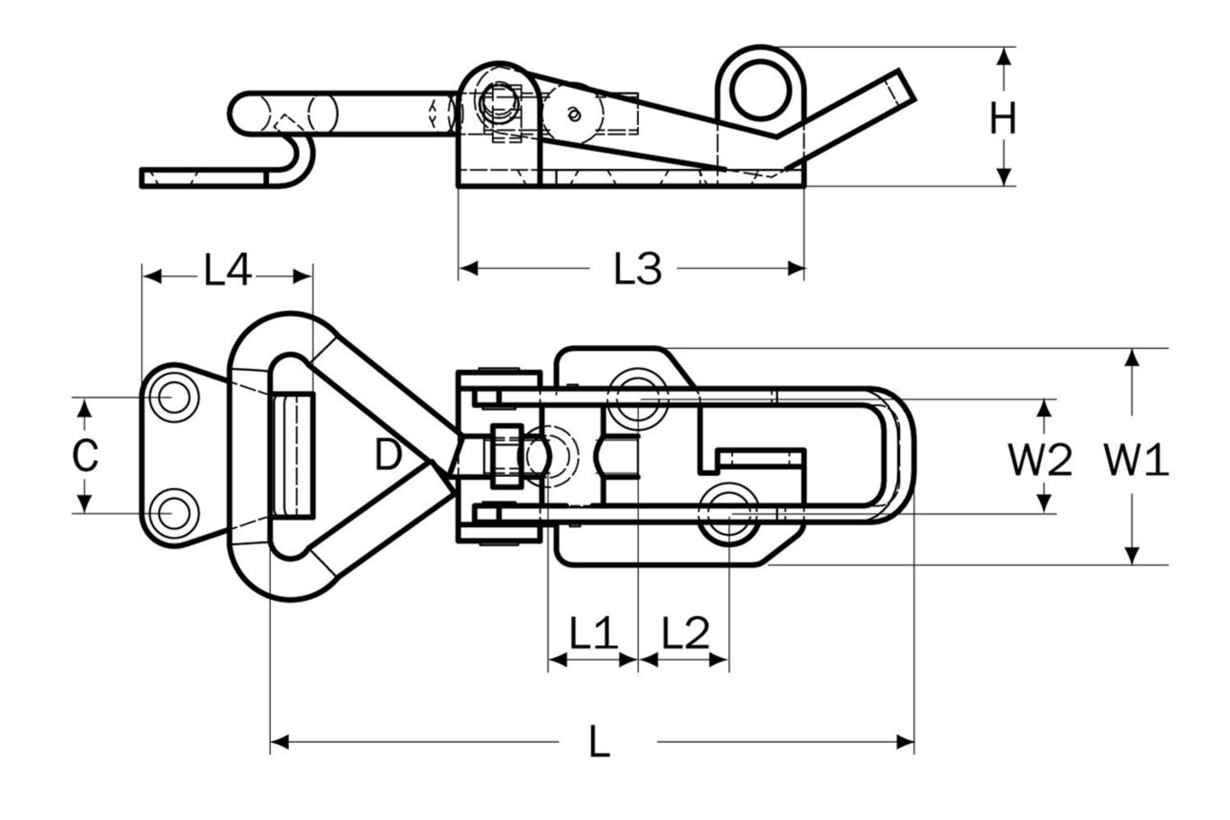
An over-center mechanism is a type of mechanical linkage that provides a locking or latching function by utilizing a specific geometric configuration. Most of us instantly know when we see something like the image above. The key components of an over-center mechanism include:
Three pivot points
Two fixed-length links
One variable-length link
The mechanism operates on the principle of mechanical advantage, where the force required to actuate the linkage changes as it moves through its range of motion. Here's how it works:
As the mechanism approaches the "over-center" position, the force required to move it increases.
At the over-center point, all three pivot points align in a straight line.
Once the mechanism passes the over-center point, the force required decreases, creating a self-locking effect. Or ‘hyperextension’ as one might say
This behavior results in two stable positions (bi-stable) on either side of the over-center point, allowing the mechanism to snap into place and remain locked until sufficient force is applied to move it back over the center. In this state the mechanism has stored elastic potential energy. Over-center mechanisms are commonly used in various applications, including:
Latches on tool cases and toolboxes
Vise grips or locking pliers
Folding chairs and tables
Safety gates and barriers
Clamping mechanisms in welding fixtures and jigs
Gas struts for assisted opening and closing of hatches or doors
Toggle switches
Locking mechanisms in furniture
The design of an over-center mechanism requires careful consideration of factors such as required force, travel distance, and the size and shape of the links and pivoting joints. By understanding and manipulating the over-center principle, engineers can create robust locking mechanisms or devices that release significant potential energy with minimal input force.
Thread Forming (as opposed to thread cutting)

Thread forming and thread cutting are two distinct methods used to create threads in materials, typically for screws or bolts:
Thread Forming
This process displaces material around a pilot hole causing the metal to flow and conform to the shape called ‘plastic deformation’. No material is removed during this process.
Advantages
Produces a zero-clearance fit, which enhances resistance to loosening.
Leaves no chips or debris, making it ideal for applications where cleanliness is critical.
Creates stronger threads due to the cold-working (or work hardening) effect on the material
Often eliminates the need for additional locking devices, such as lock washers.
Applications: Commonly used in sheet metal or material where minimizing internal stresses is important.
Shape Circa
The stories of fashioning small architectural projects in chronological order by Shape.
Featured Posts

